Do it yourself
Life hacks, master classes, useful tips, recipes.
home » Electronics » DIY power supply " Laboratory power supply
Good day to all! Today I would like to present to your attention the Laboratory Power Supply (LBP). I think every novice radio amateur is faced with the problem of obtaining the necessary voltage for one or another of his homemade products, because each device requires a different voltage. I also encountered the same problem the other day. It was necessary to power a homemade amplifier, but the necessary voltage was not at hand. Well, this is not the first homemade product I've had problems with. So I got to work.

So, we need:
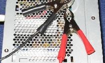
-Case (you can buy a ready-made one, or you can take it from a computer power supply like I did)
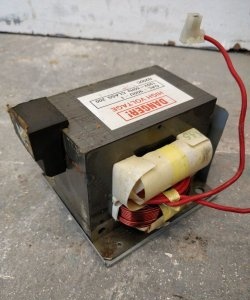
-Transformer with output voltages up to 30V and current up to 1.5 amperes (I took a more powerful trans as 1.5A is not enough for me)
-Simple set of radio components:
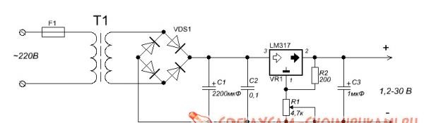
-Diode bridge 3A.
-Electrolytic capacitor 50V 2200uF.
-Ceramic capacitor of 0.1 microfarads (to smooth out ripples more).
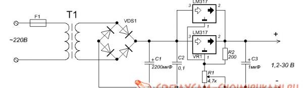
-LM317 microcircuit (in my case there are 2 such microcircuits).
-Variable resistor at 4.7 kOhm.
-Resistor at 200 ohm 0.5W.
-Ceramic capacitor 1 µF.
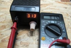
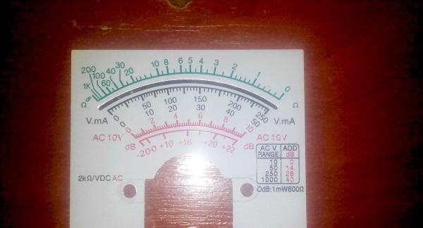
-Old analog tester (I used it as a voltmeter).
- Textolite and ferric chlorine (for etching the board).
-Terminals.
-Wires.
-Soldering accessories.
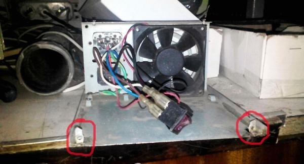
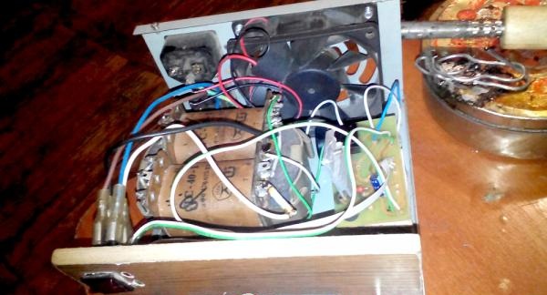
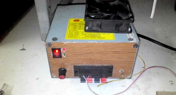
Begin! I took the case from a computer power supply. We disassemble it and take out the insides and saw off the front panel (the one from which the wires come out) as in the photo.

Laboratory power supply


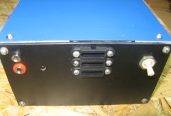
Next, we assemble it back and cut out the front panel of the future power supply from fiberboard; it might be more beautiful from plastic.

Laboratory power supply


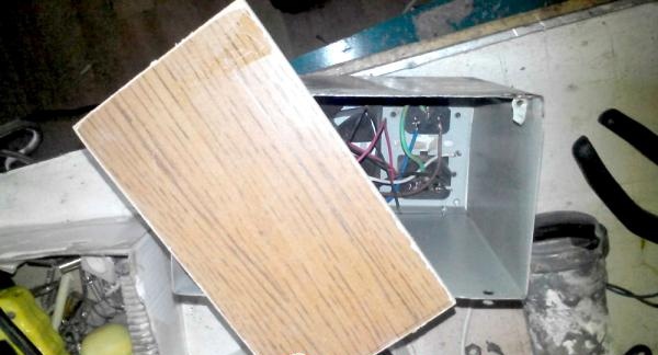
We cut off the board fasteners on one side and bend them in such a way that we can then attach the front panel we made to them.

Laboratory power supply

Laboratory power supply


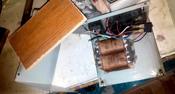
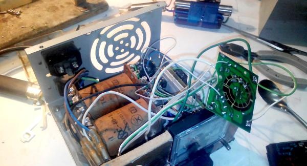
We select a place for the transformer, drill holes in the lower part of the housing and secure the transformer.

Laboratory power supply


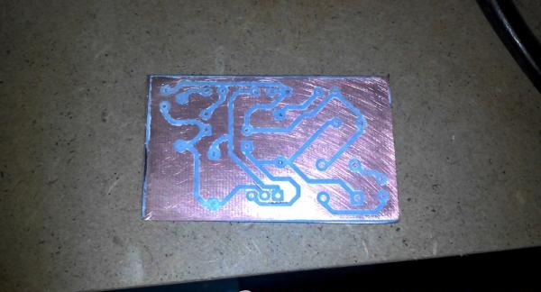
Now let's start assembling the board, first we need to etch it. We transfer the pre-printed board to the PCB.

pay


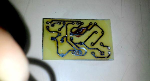
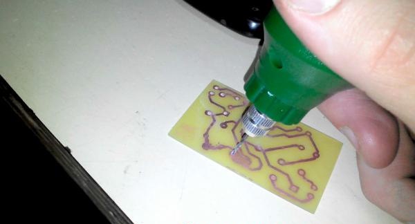
And throw it into chlorine for 10-20 minutes. After etching, we drill holes and tin the board.

pay

drill holes


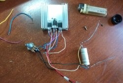
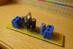
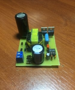
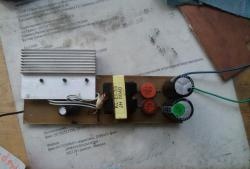
We solder the elements according to the diagram.

elements on the board

block diagram

block diagram


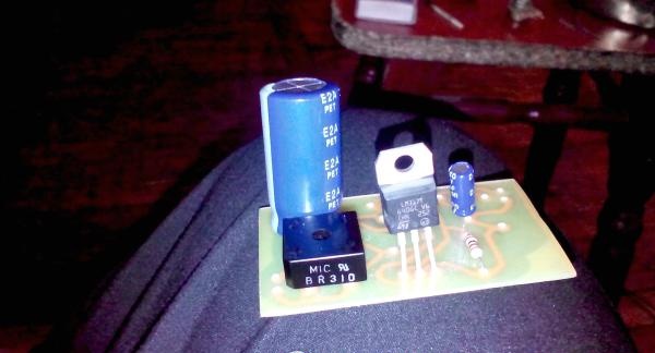
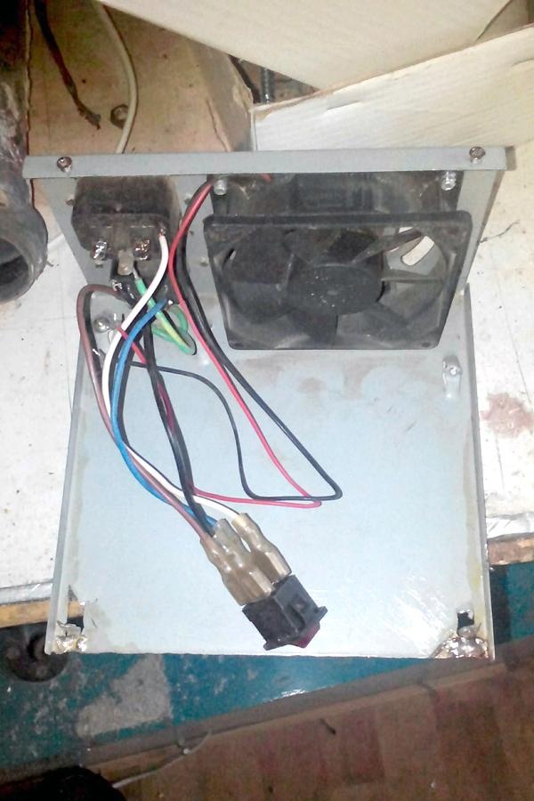
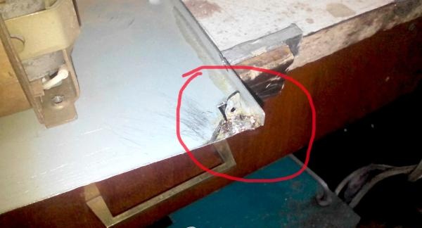
We take the wires, assemble the circuit and pack everything into the case. IMPORTANT! (the microcircuit must be installed on a radiator, since under heavy loads it gets very hot and can fail). This is what happened.

Laboratory power supply


Now you need to get a voltmeter from the old tester. To do this, simply cut off the indicator itself from the plastic case.

Laboratory power supply


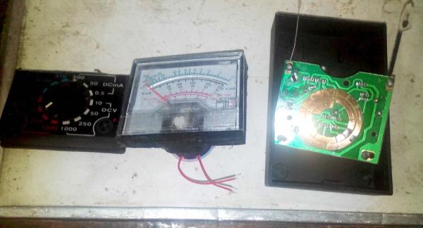
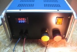
Next, you need to place a jumper on the tester board in the 50V range, cut a hole in the front panel for our voltmeter and connect the wires. We isolate our board and close the case. I installed a cooler on top to blow air over the radiator on which the microcircuit is installed.

Laboratory power supply

scale

Laboratory power supply

Laboratory power supply


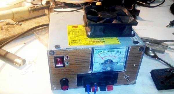
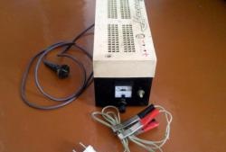
That's all! The laboratory power supply is ready! Good luck to all!
come back
Comment
  • bowtiesmilelaughingblushsmileyrelaxed relaxedsmirk
    heart_eyeskissing_heartkissing_closed_eyesflushedrelievedsatisfiedgrin
    winkstuck_out_tongue_winking_eyestuck_out_tongue_closed_eyesgrinningkissingstuck_out_tonguesleeping
    worriedfrowninganguishedopen_mouthgrimacingconfusedhushed
    expressionlessunamusedsweat_smilesweatdisappointed_relievedwearypassive
    disappointedconfoundedfearfulcold_sweatperseverecrysob
    joyastonishedscreamtired_faceangryragetriumph
    sleepyyummasksunglassesdizzy_faceimpsmiling_imp
    neutral_faceno_mouthinnocent
4 minus one =
Comments (11)
  1. igaz
    #1 igaz Guests 11 October 2015 23:14
    7
    This is anything but a laboratory power supply. Maximum supply for toys.
  2. TT
    #2 TT Guests 31 December 2015 19:06
    1
    You would have designed it using lamps, complete archaism, 21st century, but it would be a pity to throw out the old transformer from the TV, it will short-circuit and burn everything.
    1. bbbt
      #3 bbbt Guests 19 February 2022 18:29
      2
      You wouldn't be delusional, my friend. Why are you so afraid of transformers, huh? 35 years ago, any pioneer could make a transformer out of cans with his own hands, and was not afraid of anything and did not shortcut or burn anything... as they say: “there is no need to blame the mirror...”, straighten your hands and everything will be ok.
  3. Apolonik
    #4 Apolonik Guests February 14, 2016 09:21
    0
    Yes, a little old-fashioned, and very simple. As they say, what is simple does not last forever. For beginner radio amateurs this is what you need. Check every little thing. If we talk about a laboratory power supply, it is better to make it from LATR, the only thing is that you cannot joke with such a transformer, you need strong knowledge, since experiments can end tragically. I actually have everything.
  4. Sergey
    #5 Sergey Guests 4 March 2016 16:05
    0
    All this is good. But no offense, have you heard about LM350 and LM338, a digital voltmeter for example? And the build quality of the case is very sad.Although in general, the scheme is time-tested and is repeated over and over again.
  5. Max
    #6 Max Guests August 5, 2016 01:19
    6
    TT,
    Why will he short-circuit if his hands are not made of w...s like some people?
  6. Kai
    #7 Kai Guests 13 December 2016 16:21
    26
    There is nothing more reliable than a transformer-rectifier-stabilizer circuit, but it’s old-fashioned, but the efficiency is low, and the dimensions are large, etc., but your favorite toy doesn’t puff like an impulse generator, you need more current - install a more powerful stabilizer, but in general, to each his own, but to criticize No need!
    1. GTS
      #8 GTS Guests 27 May 2018 16:51
      1
      For most amateur radio designs, a switching laboratory power supply with a switching stabilizer will do. For high output voltages and currents, the size gain and savings on heat sinks will be very noticeable.
  7. Eugene
    #9 Eugene Guests 2 March 2019 21:27
    4
    A completely suitable design for a beginner, simple and cheap, stability is also okay. After all, not everyone needs 1% accuracy and stability. Well, the radiator must dissipate at least 30 W. And of course in the second scheme, turn it on like this You can’t have two microcircuits; no two microcircuits are the same. It’s better to install a powerful transistor instead of the top microcircuit.
  8. fcfc
    #10 fcfc Guests 10 July 2019 18:03
    0
    bullshit in one word
  9. Guest Alexey
    #11 Guest Alexey Guests July 31, 2022 11:25
    0
    I read the comments, they were just smart people, there’s nothing more to say. If you have already outgrown this, then there is no point in flooding here.

Electronics | Page 4 | Do it yourself

The most reliable connection of wires without a soldering iron

How to make a remote controlled faucet

Cover for dishes “Chicken” | Do it yourself

«Do it yourself - with your own hands» - a site of interesting homemade products made from scrap materials and items at home. Step-by-step master classes with photos and descriptions, technologies, life hacks - everything a real master or just a craftsman needs for needlework. Crafts of any complexity, a large selection of directions and ideas for creativity.

We recommend reading

Washing machine error codes