DIY do it yourself
Master classes, instructions, useful tips, recipes.
» » »Simple soldering iron temperature controller
For a decent quality of soldering work, a home foreman, and even more so a radio amateur, a simple and convenient temperature regulator for a soldering iron tip will come in handy. For the first time, I saw a device diagram in the magazine Young Technician in the early 80's, and having collected several copies, I still use them.

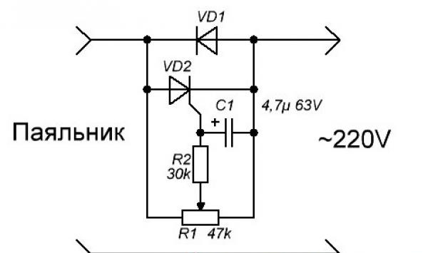
regulator circuit


To build the device you will need:
diode 1N4007 or any other, with a permissible current of 1A and a voltage of 400 - 600V.
thyristor KU101G.
- 4.7 microfarad electrolytic capacitor with an operating voltage of 50 - 100V.
- resistance 27 - 33 kilo-ohms with an allowable power of 0.25 - 0.5 watts.
Variable resistor 30 or 47 kilo-ohms SP-1, with a linear characteristic.

soldering iron temperature regulator


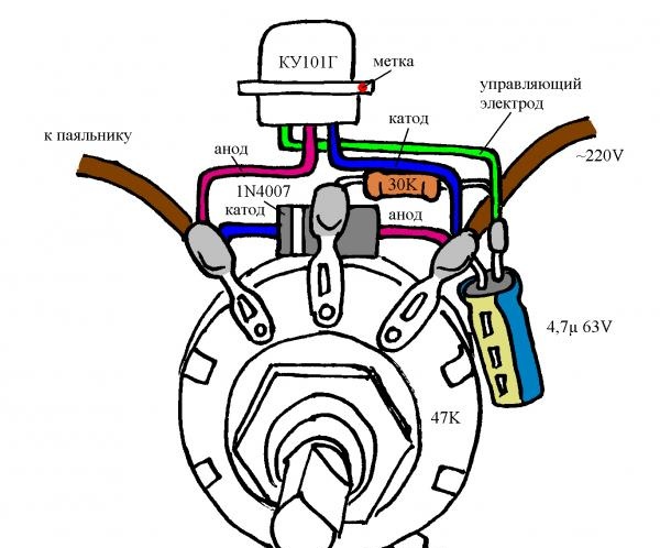
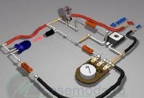
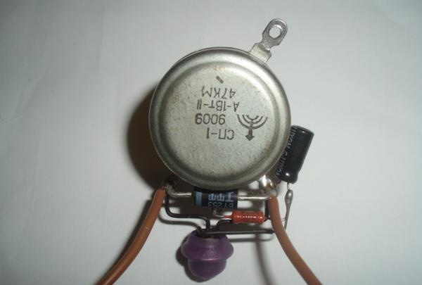
For simplicity and clarity, I drew the placement and interconnection of parts.
soldering iron temperature regulator


Before assembly, it is necessary to isolate and shape the findings of the parts. We put insulating tubes 20 mm long on the thyristor terminals, 5 mm on the terminals of the diode and resistor. For clarity, you can use colored PVC insulation, removed from suitable wires, or sit down shrink. Trying not to damage the insulation, we bend the conductors, guided by a drawing and photographs.

Simple soldering iron temperature controller


All parts are mounted on the terminals of the variable resistor, connecting to the circuit with four soldering points. We bring the conductors of the components into the holes on the terminals of the variable resistor, trim and solder everything. We shorten the conclusions of the radioelements. The positive terminal of the capacitor, the thyristor control electrode, the resistance terminal, are connected together and fixed by soldering. The thyristor case is an anode, for safety, we isolate it.

soldering iron temperature regulator


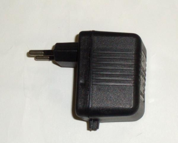
To give the design a finished look, it is convenient to use the housing from the power supply with a mains plug.

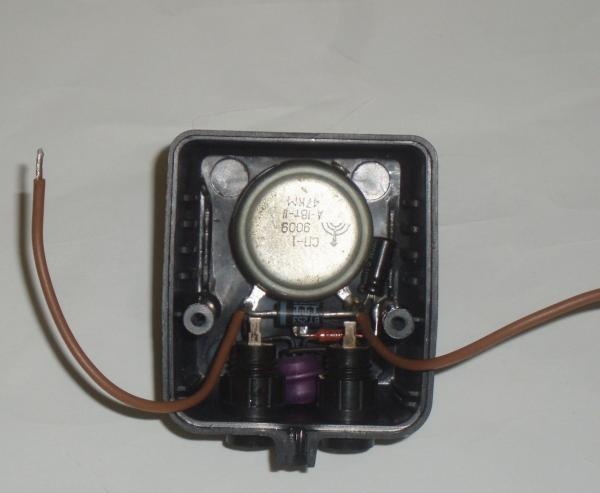
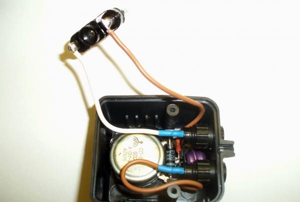
temperature controller inside


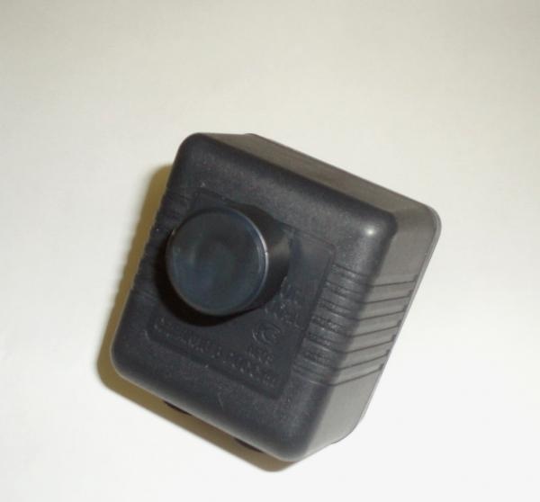
On the upper edge of the body we drill a hole with a diameter of 10 mm. We insert the threaded part of the variable resistor into the hole and fix it with a nut.

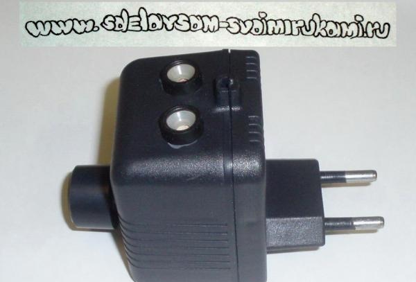
To connect the load, I used two connectors with holes for pins with a diameter of 4 mm. On the body we mark the centers of the holes, with a distance between them of 19 mm. In drilled holes with a diameter of 10 mm. insert the connectors, fix with nuts. We connect the plug on the case, the output connectors and the assembled circuit, the solder points can be protected by heat shrink. For a variable resistor, it is necessary to select a handle made of insulating material of such shape and size to close the axis and nut. We assemble the case, securely fix the knob.

Simple soldering iron temperature controller


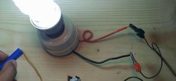
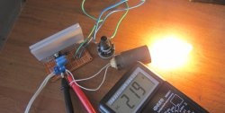
We check the regulator by connecting an incandescent lamp of 20 - 40 watts as a load. By turning the knob, we are convinced of a smooth change in the brightness of the lamp, from half brightness to full heat.

Simple soldering iron temperature controller


When working with soft solders (for example, POS-61), an EPSN 25 soldering iron, 75% of the power is sufficient (the position of the regulator knob is approximately in the middle of the stroke). Important: on all elements of the circuit there is a supply voltage of 220 volts! Observe electrical safety precautions.

Author: Sergey Lavrentiev
come back
Comments (34)
  1. ALPom
    #1 ALPom Guests October 24, 2014 8:48 p.m.
    0
    But there is no interference on the network from such a regulator?
  2. -serg-
    #2 -serg- Guests October 25, 2014 17:15
    0
    With asymmetric energy consumption from two half-waves of alternating voltage, interference will inevitably occur.
    But when regulating not a lot of power, 15-25 watts, in my experience, there is no noticeable effect of interference on modern technology (LCD TV, computer, music center).
  3. Dmitry
    #3 Dmitry Guests October 31, 2014 1:07 p.m.
    1
    The constant applied voltage in the closed state at KU101G is only 80 volts. It will not be enough! Maybe it's better to use KU712A2? Dimensions are not much larger, but it is possible to regulate a much larger load.
  4. -serg-
    #4 -serg- Guests November 2, 2014 00:15
    0
    The resistance of a 25-watt soldering iron is slightly more than 2 kilo-ohms, the current passing through it will not exceed 115 milliamps.
    This is a gentle mode for the circuit, the voltage between the cathode and the anode of the thyristor varies from 30 to 110 volts.
    The oldest instance of this design has been working for more than a quarter of a century. For a slightly more significant load, you can use the KU101E thyristor (150 volts).
  5. Edward
    #5 Edward Guests February 12, 2015 15:12
    0
    More powerful thyristors such as bta12-600 (12 amperes 600 volts) can be used? And a modern variable resistor if used combined with a switch? And can this circuit be used as a night lamp for a 25 watt light bulb)
  6. = Andrey =
    #6 = Andrey = Guests February 18, 2015 16:57
    2
    And if instead of using a soldering iron use a 500 W boiler, then what parts need to be changed ??? or is this circuit not suitable ???
  7. -serg-
    #7 -serg- Guests March 30, 2015 21:26
    2
    When using a powerful thyristor, for example KU202N mounted on a radiator, you can adjust the load to 1 kilowatt.
    But such a circuit will become a source of tangible interference in the electrical network.
    A two-kilowatt controller on a powerful triac, which does not interfere, can be removed (or assembled according to the scheme) from a household vacuum cleaner. (LG, Samsung, etc.).
  8. Victor Lapshev
    #8 Victor Lapshev Guests May 13, 2015 15:10
    1
    KU104G is suitable?
  9. Taras
    #9 Taras Guests May 18, 2015 09:42
    4
    Do I understand correctly that if you put a switch in series with the VD1 diode, then breaking the circuit on the VD1 diode, the adjustment will occur 0-50%, and closing the circuit on it, the adjustment will be 50-100%?
  10. -serg-
    #10 -serg- Guests May 24, 2015 13:24
    0
    KU104G is quite suitable.
    The control of one half-wave generates tangible interference, if smooth control of the power of 0-100% is required, perhaps it was worth using the dimmer circuit on the triac.
    [center] [img] http://washerhouse.com/3/en/pictures_users/1/42.jpg [/ img] [/ center]
  11. Maksim
    #11 Maksim Guests October 23, 2015 20:33
    0
    Sorry to me my stupid question, but do you need all this? Why do we need a diode, capacitor, capacitor, etc.? Why can not do only potentiometer and radiator?
  12. -serg-
    #12 -serg- Guests November 5, 2015 23:55
    1
    Power control by changing the resistance, a long-known method, is implemented using a rheostat.
    [center] [img] http://washerhouse.com/3/en/pictures_users/1/43.jpg [/ img] [/ center]
    Such a design, which is noticeably warming up, being energized by the mains supply, is difficult to place in a safe manner, in a small box with a convenient control handle.
  13. Alexander
    #13 Alexander Guests November 25, 2015 01:37
    2
    Hello. And what is the best way to adapt this circuit for a 60W soldering iron? Do I need to recount the values ​​of the elements (and how exactly) and use a different thyristor? How is the feature defined after which the load is critical and “the circuit becomes a source of tangible interference in the electrical network”? Thank you in advance.
  14. -serg-
    #14 -serg- Guests December 18, 2015 01:46
    0
    If you install a KU202N thyristor in the circuit, you can adjust the power up to 400 watts.
    It is possible to assess the level of interference (as well as the tolerance of neighbors to them) by the magnitude of the characteristic distortions in the television image.
  15. Leonid
    #15 Leonid Guests February 7, 2016 11:08
    1
    Thyristor converters interfere. Resistive control consumes excess power. I consider the most "harmless" (although requiring additional space on the table, or under the table) voltage regulation at the load using autotransformers LATR-1 (with a load of up to 100 W) and LATR-2 (with a load of up to 800 W).
  16. Valentin Goncharuk
    #16 Valentin Goncharuk Guests February 7, 2016 22:13
    1
    But isn’t it easier to get a hole (voltage regulator in apartment lighting systems) in any electric goods store and do not fool with its manufacture.! I’ve been using them on soldering irons for about 6-7 years now - a 40W Chinese TIAO GUFNG through passage. For more powerful consumers, up to 800 W installation, for hidden wiring. Regarding radio interference, they are, but not very significant, the transistor at a distance of 2-3 m. They do not accept.
  17. -serg-
    #17 -serg- Guests February 11, 2016 10:23
    3
    It is inconvenient to work with LATR on “visiting sessions” (it’s hard to drag).
    The dimmer is convenient, it can be used for its intended purpose (for example, to regulate the brightness of a floor lamp), involving in working with a soldering iron as necessary.
    The design from the article is intended for those who want to independently assemble a simple and low-budget regulator for a “soldering iron with a copper tip without coating”.
    Professionals and serious hams use soldering stations.
  18. Denis
    #18 Denis Guests February 20, 2016 2:36 p.m.
    0
    Tell me, is KU101B weak? I just found them
    And the resistor SP3-30K-47K MV0.125 9008 with a switch
  19. -serg-
    #19 -serg- Guests February 22, 2016 11:19
    0
    SP3-30K-47K is quite suitable.
    The thyristor is connected in series with the load. The soldering iron has a power of 15 -25 watts, the resistance is quite large and the voltage drop on it will be noticeable.
    The thyristor KU101B has a permissible closed voltage of 50 volts, in principle, it will work with a low-power load (bearing in mind the safety factor characteristic of Soviet components).
    1. Konstantin
      #20 Konstantin Guests December 8, 2018 00:40
      1
      I need the simplest circuit (without a midpoint) "Diode-thyristor rectifier with a control circuit for the welding machine" in order to regulate the current not by the primary, but by the secondary, since I wound a winding in the welding trance to pull 30v wire (for a homemade p-machine ) PLIZ !!! If possible, I will be very grateful. It is possible to My E-mail:
  20. Alexander
    #21 Alexander Guests March 19, 2016 16:44
    0
    Hello, is this circuit suitable for 36 volts? And can I use the ku202m?
  21. Grig
    #22 Grig Guests April 1, 2016 21:34
    0
    Can you use a dimmer when using a soldering iron with a "ceramic" tip?
  22. -serg-
    #23 -serg- Guests April 2, 2016 19:18
    2
    For 36 volts, you need a different regulator. KU202M can be used.
  23. Igor
    #24 Igor Guests August 12, 2016 16:37
    0
    Hello. And this circuit will fit a 75 watt soldering iron.
  24. -serg-
    #25 -serg- Guests September 7, 2016 20:12
    0
    The circuit is suitable, but it is advisable to use a more powerful thyristor.
    Of course, the interference will increase.
  25. Yang
    #26 Yang Guests October 11, 2016 19:42
    1
    So you can put the capacitor before the adjustment circuit. Volts at 400 and high capacitance to smooth out interference.
  26. Sergey
    #27 Sergey Guests December 21, 2016 08:45
    0
    Is it possible to replace the electrolyte with a simple capacitor?
  27. VN
    #28 VN Guests December 25, 2016 20:35
    0
    [b] sergey [/ b], but why replace him? The electrolyte has a smaller size. This is the meaning of the whole structure.
    1. maga
      #29 maga Guests December 22, 2017 21:06
      0
      Everything works, the triac from the New Year's garland, in my PCR406, for a 20-watt soldering iron is normal, I have been using it for six months.
  28. Fedor
    #30 Fedor Guests July 15, 2018 1:07 p.m.
    0
    I assembled it on PCR406, I don’t remember exactly, from the New Year's garland, everything works, thanks.
  29. Gennady
    #31 Gennady Guests March 5, 2019 12:42
    1
    I collected this shemka back in 1983! It still works.
  30. Alexander
    #32 Alexander Guests March 12, 2019 01:25
    0
    What interference, what are you talking about, there isn’t enough detail in the seme, so 220 volts goes through R = 1, and when you try to adjust to the extreme position there will be a short circuit on it and there will be big broads
    1. -serg-
      #33 -serg- Guests March 15, 2019 11:17 p.m.
      0
      Take a closer look, the circuit is a two-terminal circuit connected in series with the load. all current flows through VD1, VD2. What a "babah" will not be!
      1. Guest Andrey
        #34 Guest Andrey Guests July 10, 2019 07:50
        0
        Hello. Tell me, instead of the SP-1, can I use the WTH118 series potentiometer (47kΩ, 2W)?

Read also

Error codes for washing machines