Do it yourself
Life hacks, master classes, useful tips, recipes.
home » Electronics » DIY power supply » Car battery charger
Every motorist sooner or later has problems with the battery. I did not escape this fate either. After 10 minutes of unsuccessful attempts to start my car, I decided that I needed to purchase or make my own charger. In the evening, after checking out the garage and finding a suitable transformer there, I decided to do the charging myself.

transformer


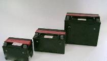
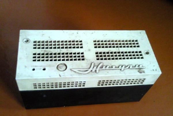
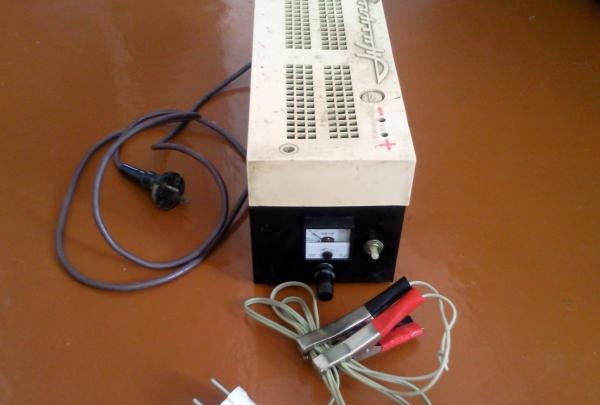
There, among the unnecessary junk, I also found a voltage stabilizer from an old TV, which, in my opinion, would work wonderfully as a housing.

Charger


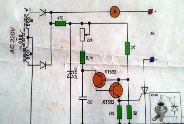
Having scoured the vast expanses of the Internet and really assessed my strengths, I probably chose the simplest scheme.

charger circuit


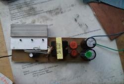
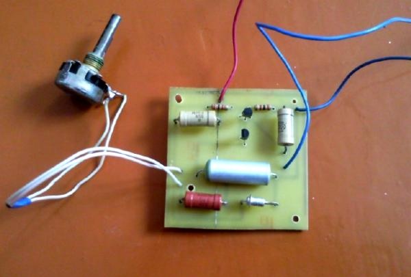
After printing out the diagram, I went to a neighbor who is interested in radio electronics. Within 15 minutes, he collected the necessary parts for me, cut off a piece of foil PCB and gave me a marker for drawing circuit boards. Having spent about an hour, I drew an acceptable board (the dimensions of the case allow for spacious installation). I won’t tell you how to etch the board, there is a lot of information about this. I took my creation to my neighbor, and he etched it for me.In principle, you could buy a circuit board and do everything on it, but as they say to a gift horse...
Having drilled all the necessary holes and displayed the pinout of the transistors on the monitor screen, I took up the soldering iron and after about an hour I had a finished board.

charger circuit


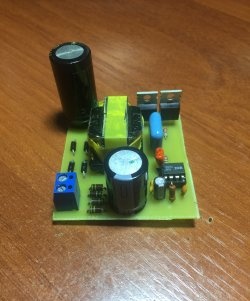
A diode bridge can be purchased on the market, the main thing is that it is designed for a current of at least 10 amperes. I found D 242 diodes, their characteristics are quite suitable, and I soldered a diode bridge on a piece of PCB.

diode bridge


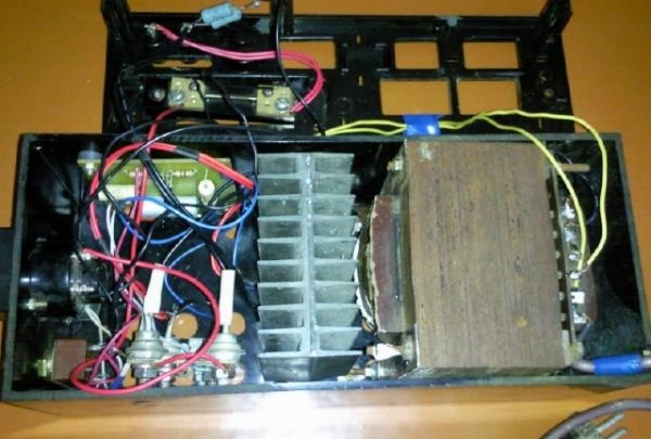
The thyristor must be installed on a radiator, since it gets noticeably hot during operation.

charger thyristor


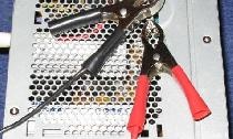
Separately, I must say about the ammeter. I had to buy it in a store, where the sales consultant also picked up the shunt. I decided to modify the circuit a little and add a switch so that I could measure the voltage on the battery. Here, too, a shunt was needed, but when measuring voltage, it is connected not in parallel, but in series. The calculation formula can be found on the Internet; I would add that the dissipation power of the shunt resistors is of great importance. According to my calculations, it should have been 2.25 watts, but my 4-watt shunt was heating up. The reason is unknown to me, I don’t have enough experience in such matters, but having decided that I mainly needed the readings of an ammeter, and not a voltmeter, I decided on it. Moreover, in voltmeter mode the shunt noticeably warmed up within 30-40 seconds. So, having collected everything I needed and checked everything on the stool, I took up the body. Having completely disassembled the stabilizer, I took out all its contents.

transformers


Having marked the front wall, I drilled holes for the variable resistor and switch, then using a small diameter drill around the circumference I drilled holes for the ammeter. Sharp edges were finished with a file.

radiator


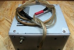
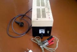
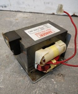
After racking my brains a bit over the location of the transformer and radiator with thyristor, I settled on this option.

Charger


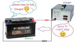
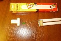
I bought a couple more crocodile clips and everything is ready to charge. The peculiarity of this circuit is that it only works under load, so after assembling the device and not finding voltage at the terminals with a voltmeter, do not rush to scold me. Just hang at least a car light bulb on the terminals, and you will be happy.

Car charger


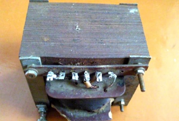
Take a transformer with a voltage on the secondary winding of 20-24 volts. Zener diode D 814. All other elements are indicated in the diagram.
come back
Comment
  • bowtiesmilelaughingblushsmileyrelaxed relaxedsmirk
    heart_eyeskissing_heartkissing_closed_eyesflushedrelievedsatisfiedgrin
    winkstuck_out_tongue_winking_eyestuck_out_tongue_closed_eyesgrinningkissingstuck_out_tonguesleeping
    worriedfrowninganguishedopen_mouthgrimacingconfusedhushed
    expressionlessunamusedsweat_smilesweatdisappointed_relievedwearypassive
    disappointedconfoundedfearfulcold_sweatperseverecrysob
    joyastonishedscreamtired_faceangryragetriumph
    sleepyyummasksunglassesdizzy_faceimpsmiling_imp
    neutral_faceno_mouthinnocent
4 minus one =
Comments (6)
  1. Alexander
    #1 Alexander Guests 22 February 2016 12:53
    3
    Hello, how can I configure it so that at low current (less than 1 ampere) the voltage is 14.4-14.8 volts
  2. Nikolay
    #2 Nikolay Guests 25 December 2016 15:27
    4
    Alexander,
    put an electrolytic capacitor at the output!
  3. popvovka
    #3 popvovka Guests February 25, 2017 11:40
    3
    Nikolay,
    So tell me, what is the electrolyte for?
    I’ll say in advance that it’s not needed there at all and the battery won’t do anything!
    And yet, the car with the generator has the same type of current as this charger.
  4. Eugene
    #4 Eugene Guests June 4, 2017 09:16
    3
    popvovka,
    Not at all like that, your ammeter does not correctly indicate the charging current in this circuit. Find the peak ammeter and see the difference...
  5. Guest Yuri
    #5 Guest Yuri Guests 5 February 2018 10:09
    11
    A long time ago in the magazine "Radio" I found a circuit diagram for a battery charger. I made this device and still use it today. It can be called a battery charging current stabilizer. The current does not change either from fluctuations in the network voltage or from the degree of battery charge. He is always the same.
    You need a transformer with a secondary voltage of at least 36 volts. The lower the secondary voltage, the larger the capacitor capacity required, i.e. their number. Connect capacitors for alternating current with a voltage of at least 500 volts in series with the PRIMARY winding of the transformer. Install a diode bridge in the secondary winding. That's all. Connect the battery to the secondary circuit, measure the current and mark it on the switch-switch of the device's network. The larger the capacitance of the capacitor, the greater the rectified secondary current (and it will always be this way, regardless of anything). This way you can mark several currents on the switch, whichever one you like. The charger is normal, increased for faster charging and small, about 1 ampere to remove sulfation from the battery. They charge an already charged battery for about one hour. You can install a voltmeter at the output of the charger to monitor battery charging (in addition to monitoring its “boiling”). An ammeter is not needed. The current was measured by you at the time of adjustment and it will no longer change.This device does not operate without load or while loaded with decent resistance. It operates in near-short-circuit or short-circuit mode. It is not afraid of this.
  6. Guest Victor
    #6 Guest Victor Guests 1 April 2019 12:36
    3
    chatter - in the diagram there is a half-bridge with a middle point - in the pictures there is a bridge! 24 on the mosquito - from the bridge 25-26 volts? plus lit-32v? on a 12v battery? Buy a goose at the market and give it its brains!

Bamboo sconce | Do it yourself

How to reliably plant an ax in the old-fashioned way with your own hands

Master class heart pendant “Spring” | Do it yourself

Built-in mini sauna in a private house

«Do it yourself - with your own hands» - a site of interesting homemade products made from scrap materials and items at home. Step-by-step master classes with photos and descriptions, technologies, life hacks - everything a real master or just a craftsman needs for needlework. Crafts of any complexity, a large selection of directions and ideas for creativity.

We recommend reading

Washing machine error codes