Of course, you can buy a ready-made memory. There are a great variety of them on sale now and for every taste. But their price is unlikely to satisfy a novice radio amateur or someone who is able to make a charger with their own hands.
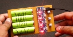
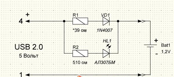
I decided to repeat this scheme, but make a charger to charge two batteries at once. The output current of USB 2.0 is 500 mA. So you can safely connect two batteries. The modified diagram looked like this.
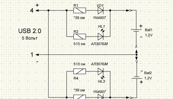
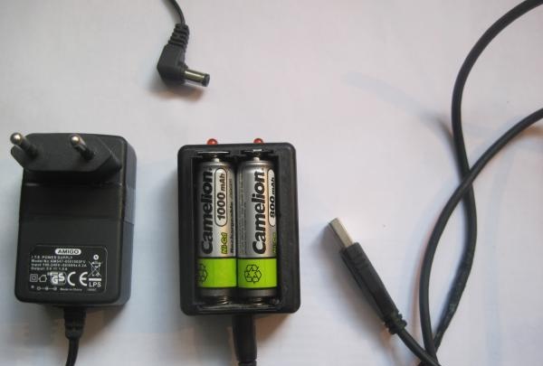
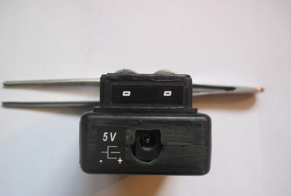
I also wanted it to be possible to connect an external 5 V power supply.
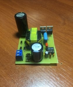
The circuit contains only eight radio components.
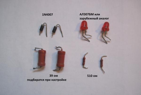
The tools you will need are a minimum radio amateur set: soldering iron, solder, flux, tester, tweezers, screwdrivers, knife.Before soldering radio components, they must be checked for serviceability. For this we need a tester. Resistors are very easy to check. We measure their resistance and compare it with the nominal value. How to test a diode and Light-emitting diode there are many articles on the Internet.
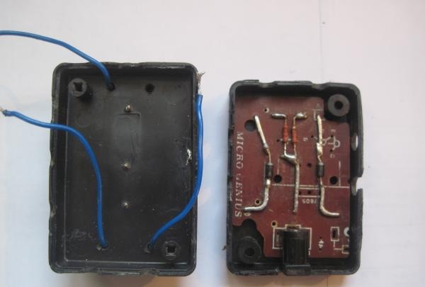
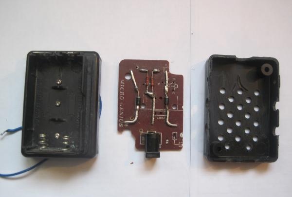
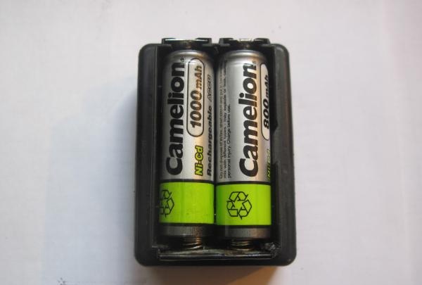
For the case I used a plastic case measuring 65*45*20 mm. The battery compartment was cut out from a children's Tetris toy.
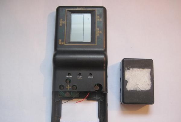
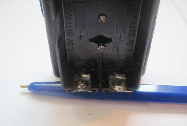
I’ll tell you more about redesigning the battery compartment. The point is that initially
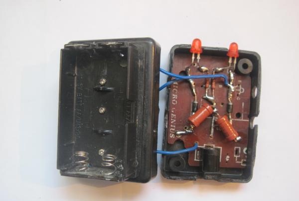
The pros and cons of the battery power terminals are set oppositely. But I needed two insulated positive terminals to be located at the top of the compartment, and one common negative terminal at the bottom. To do this, I moved the lower positive terminal to the top, and cut out the common negative terminal from tin, soldering the remaining springs.
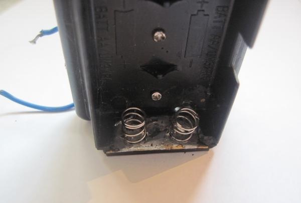
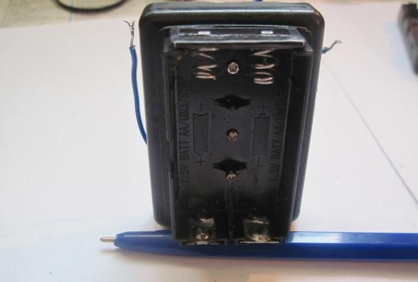
When soldering the springs, I used soldering acid as a flux in compliance with all safety regulations. Be sure to rinse the soldering area in running water until traces of acid are completely removed. I soldered the wires from the terminals and passed them inside the case through the drilled holes.
The battery compartment was secured to the cover of the case with three small screws.
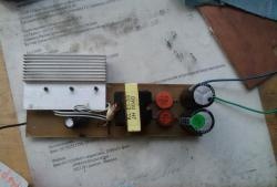
I cut the board out of an old modulator for the Dandy game console. Removed all unnecessary parts and printed wiring tracks. I left only the power socket. I used thick copper wire as new tracks. I drilled holes in the bottom cover for ventilation.
The finished board fit tightly into the case, so I did not secure it.
After installing all the radio components in their places, we check the correct installation and clean the board from flux.
Now let's unsolder the power cord and set the charging current for each battery.
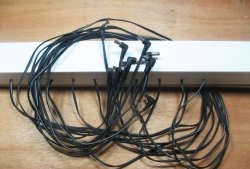
As a power cord I used a USB cord from an old computer mouse and a piece of power wire with a plug from “Dandy”.
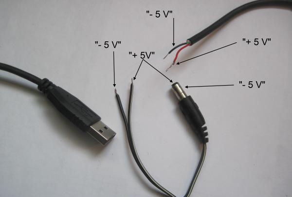
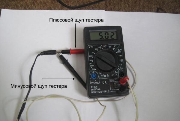
The power cord needs to be given special attention. In no case should you confuse “+” and “-”. On my plug, the “+” power supply is connected to the central contact with a black wire with a white stripe. And the “-” power supply goes along the black (without stripe) wire to the outer contact of the plug. On the USB cable, “+” goes to the red wire and “-” to the black wire. We solder plus to plus and minus to minus. We carefully isolate the soldering points. Next, we check the cord for a short circuit by connecting the tester in resistance measurement mode to the plug terminals. The tester should show infinite resistance. Everything needs to be double-checked carefully to avoid burning the USB port. If everything is fine, connect our cord to the USB port and check the voltage on the plug. The tester should show 5 volts.
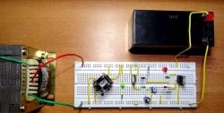
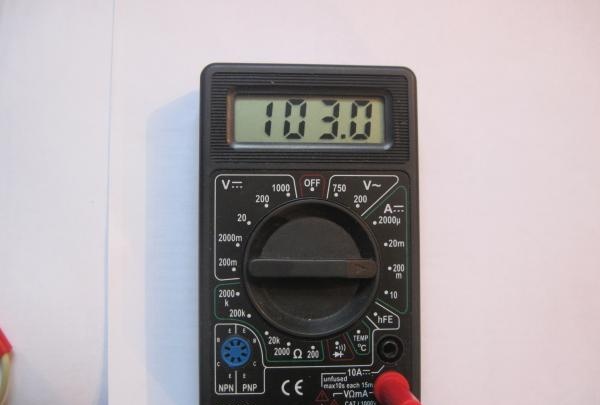
The last stage of setup is setting the charging current. To do this, we break the circuit of the VD1 diode and the “+” battery. We connect the tester into the gap in the mode of measuring the current turned on to a limit of 200 mA. The plus of the tester is for the diode, and the minus is for the battery.
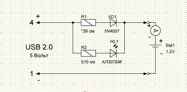
We insert the battery into place, observing the polarity, and apply power. It should light up Light-emitting diode. It signals that the battery is connected. Next, by changing the resistance R1, we set the required charge current. In our case it is approximately 100 mA. As the resistance of resistor R1 decreases, the charging current increases, and as it increases, it decreases.
We do the same for the second battery. After this we twist our body and
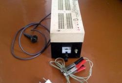
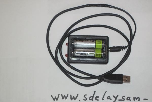
The charger is ready for use.
Since different AA batteries have different
capacity, it will take different times to charge these batteries. Batteries
capacity of 1400 mAh with a voltage of 1.2 V will need to be charged using this
circuits for approximately 14 hours, and 700 mAh batteries will require only 7 hours.
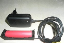
I have batteries with a capacity of 2700 mAh. But I didn’t want to charge them for 27 hours from the USB port. That's why I made a power socket for an external 5 volt 1A power supply that I had lying around.
Here are some more photos of the finished device.
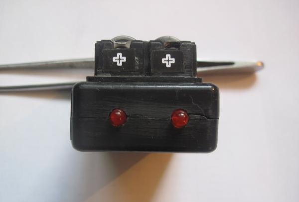
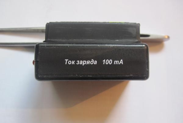
The stickers were created using FrontDesigner 3.0. Then I printed it on a laser printer. I cut it out with scissors and pasted it with the front side on thin tape 20 mm wide. I cut off the excess tape. I used a glue stick as glue, having previously smeared it on both the sticker and the place where it was glued. I don’t know yet how reliable this is.
Now the pros and cons of this scheme.
The advantage is that the circuit does not contain scarce and expensive parts and is assembled literally on the knee. It is also possible to power it from a USB port, which is important for beginner radio amateurs. No need to rack your brains about where to power the circuit. Despite the fact that the circuit is very simple, this charging method is used in many industrial chargers.
You can also switch the charging current by slightly complicating the circuit.
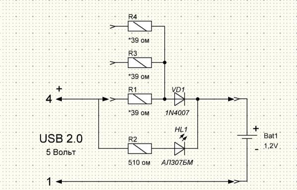
By selecting R1, R3 and R4, you can set the charging current for batteries of different capacities, thereby providing the recommended charging current for a given battery, which is usually equal to 0.1C (C-capacity of the battery).
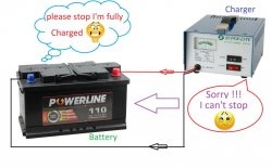
Now the cons. The biggest one is the lack of stabilization of the charging current. That is
When the input voltage changes, the charging current will change. Also, if there is an installation error or a short circuit in the circuit, there is a high probability of burning the USB port.